TX00CQ31 –Digital Signal Processing
Study 6: Analog Filters and applying DSP
tricks
|
Read these instructions first!
|
Number |
Questions |
Write your answer in this column |
Hints |
|
Q1 |
Generate filter
parameters for 4’th degree Butterworth, low-pass filter, cutoff
frequency 1.5 kHz, and sampling rate 8000 Hz. Draw
the Argand’s diagram. |
Commands:
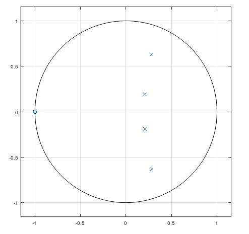 |
butter zplane |
|
Q2 |
Stem-plot
few first values of the impulse response of the system, and verify from the
plot that this is indeed an IIR-system. |
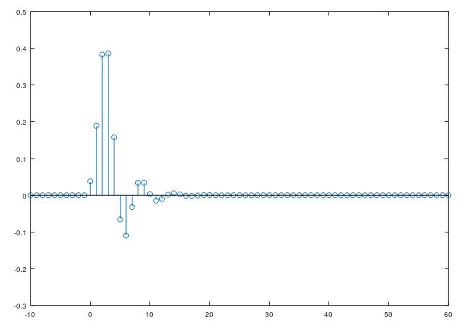 |
filter |
|
Q3 |
Generate
filter parameters for 4’th degree Elliptic, low-pass filter, cutoff
frequency 1.5 kHz, passband ripple 4 dB, attenuation 60 dB and sampling rate
8000 Hz. Compare responces of Q1 and Q3 filters. What are the differencies? |
Commands:
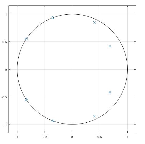 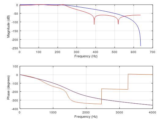 |
ellip freqz |
|
Q4 |
In this
task we demonstrate how to clean up a signal from unwanted component. First
create a signal of two sinusoidals, one with the frequency of 2p·0,05 rad/sample, and an
another with the frequency of 2p·0,47 rad/sample. Create
a moving average filter whose
length can be adjusted. Find out the optimal value of filter length which
removes the higher frequency, but passes thru the lower frequency. |
Commands:
Show the signal before and after filtering.
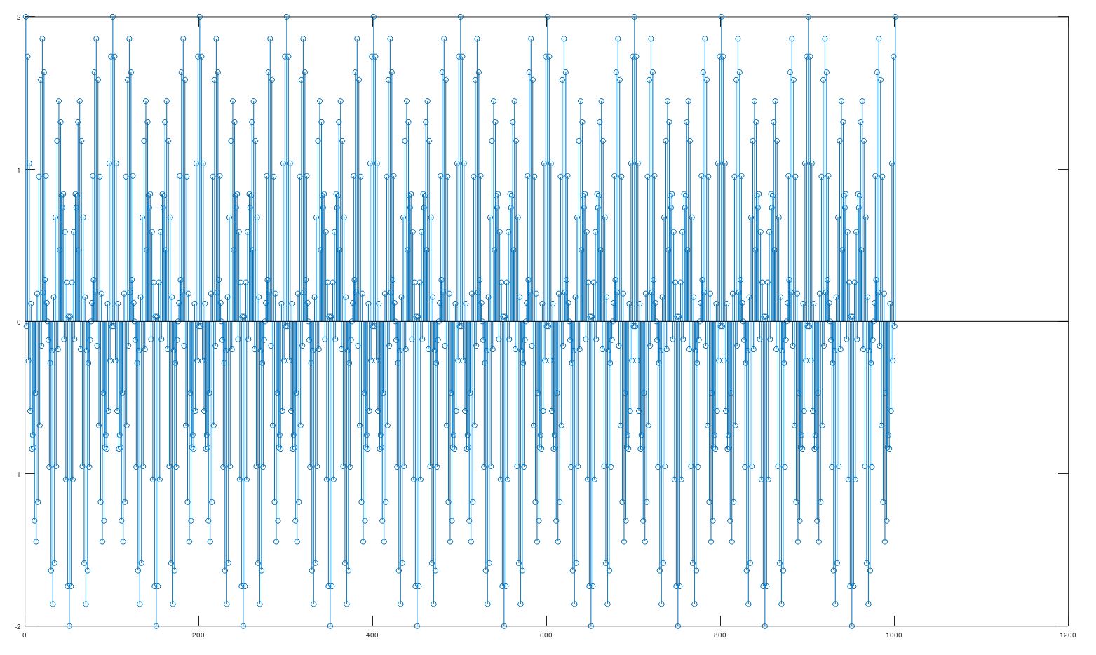
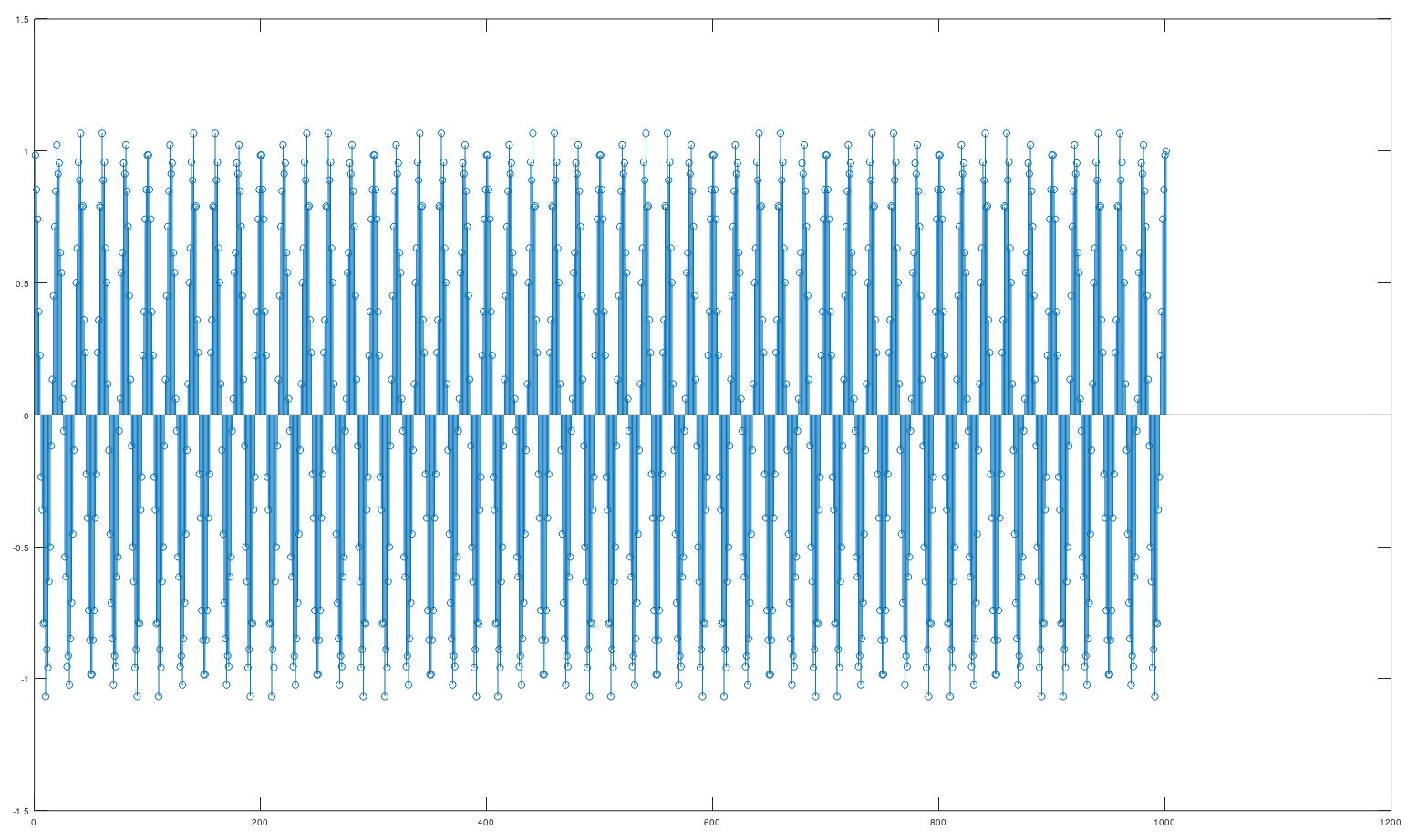 What is the optimal length M of the moving average filter.
|
ones filter |